
(click on the photos see full size photos)


Here is PCB which can be used for the board:

- This mod is based on a LM317 voltage regulator, which takes the USB's 5V and outputs 2.8V, ready to be used on the Wiimote. It DOES not destroy your wiimote, the only "hack" is a hole to pass the usb cable through (and an optional LED "power-ON" indicator light).
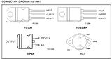
- LM317 comes in these packages and the pinouts are as shown:


Hello!
ReplyDeleteWhat you made is incredibly interesting! As it is a little complicated for me to make I'd need the picture form the other side of this...http://i202.photobucket.com/albums/aa220/klapatsimbanos/Wiimote/PSU033.jpg
Could you please post it on your blog so that I could try to make the project real to me ;-)
Cy
I am on vacations after my military service and do not have it on hand. But the components should placed exactly as this picture ONCE YOU MIRROR IT: http://i202.photobucket.com/albums/aa220/klapatsimbanos/Wiimote/wiimote_usb_PCB.jpg
ReplyDeleteThis picture was made to create the circuit on PCB, that is why it is MIRRORED. If you re-MIRROR it, you can see how the bottom of the pcb would look like and build your own.
Hope this helps.
Hi...
ReplyDeleteBest regards from Spain, great your work well done, One question can you shown, how connects the board to wiimote.
Thx alot for your work.
inigohe@gmail.com
Sorry for that Inigohe, but i am very far away from my pc at the moment.
ReplyDeleteBut check this:
1) Build this: http://i202.photobucket.com/albums/aa220/klapatsimbanos/Wiimote/wiimote_usb_PCB.jpg (it is mirrored, ready to be transfered to PCB)
2) After building this, cut it EXACTLY at its outline (thin black line that surrounds the inside parts).
3) Solder some TOUCH PADS to the big BLACK pads that are marked as WIIMOTE(+) and WIIMOTE(-). This is were the (+) and the (-) of the wiimote should contact with the (+) and (-) of the PCB. That is why you should solder something between them and the wiimote's contacts. I used a big-diameter wire (~2mm) to create the contacts.
4) Now place the PCB inside the Wiimote. The outline has edges, which will let you know which side you should put it.
Hope it helps,
thank you for your kind words
:)
So I realize this is fairly old now, but I am seriously interested in trying out this project...just got heavily into modding my wii, and this would make a super fun addition. I am fairly new to circuitry though, so I need to know...Does the wattage on the resistors matter? The images show 470/270/220 ohms, but do not mention the wattage...when I was shopping for parts they all show the ohms and wattage. Any info would be great, feel free to email at jeremy.tschudy@gmail.com
ReplyDeletePlease make sure you buy 1/8W or bulkier resistors and you will be fine!
ReplyDeleteHope it helps,
NuMcA
I saw two other designs that included capacitors I was wondering what the diiference would be between using your design and the ones with 1uf and .1uf capacitors?
ReplyDeleteinteresting circuit. Thanks. I suggest fabricated this circuit for everyone :)
ReplyDeletethanks, good circuit
ReplyDelete