
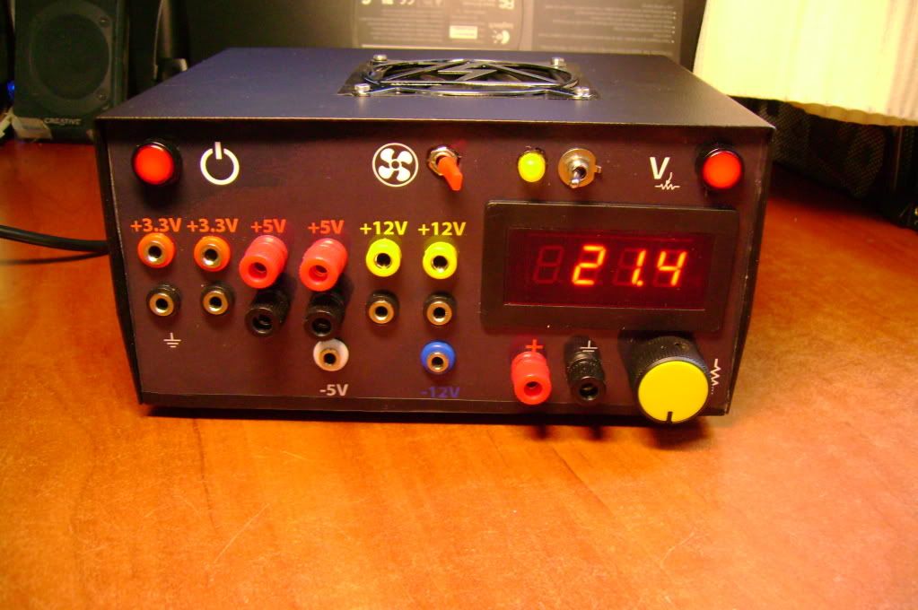
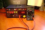
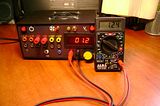
I needed a PSU (Power Supply Unit) for my electronics projects, so I modified an old ATX PSU (computers' power supply unit). It outputs a total of 400W and has a regulated variable voltage output of 1.25V to ~21.75V (DC).
 Click here to see the full slideshow
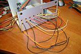
I used a LM317 voltage regulator, some switches and the original PCB of the PSU. The project turned out to be extremely easy to build, minimum soldering, finished it in 1 day!
The original PSU was a Τ & P MEIJI, Model: MEIJI 400-ATX (400W) and it now outputs:
Read more for more photos and schematics...
Click on thumbnails to see larger photos:
The schematic i used: (right click/"View image" to see full size)
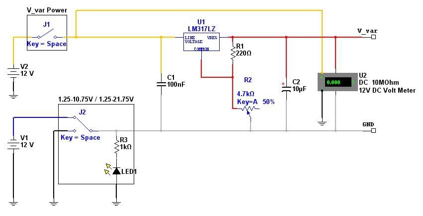
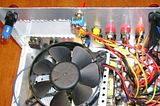
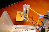
The LCD voltmeter operates on 5V, so i had to use a 2nd LM317 to get 5V from the 12V line. The small veroboard was the only thing that needed to be soldered, and it holds the 2 LM317s.
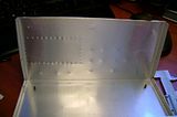
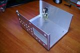
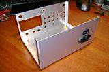
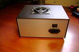
The box used was this one.


I used a LM317 voltage regulator, some switches and the original PCB of the PSU. The project turned out to be extremely easy to build, minimum soldering, finished it in 1 day!
The original PSU was a Τ & P MEIJI, Model: MEIJI 400-ATX (400W) and it now outputs:
- +3.3V, 28A
- +5V, 40A
- +12V, 18A
- -5V, 0.3A
- -12V, 0.8A
- Vvariable: 1.25V - 10.75V or stand-alone 1.25V - 21.75V
Read more for more photos and schematics...
Click on thumbnails to see larger photos:


The schematic i used: (right click/"View image" to see full size)
The LCD voltmeter operates on 5V, so i had to use a 2nd LM317 to get 5V from the 12V line. The small veroboard was the only thing that needed to be soldered, and it holds the 2 LM317s.

The box used was this one.

a standard PSU already has 5V lines, so why the need for the second LM317?
ReplyDeleteBecause if i power the LCD screen from the same 12V line that i power the variable voltage. WHEN the variable voltage output is switched ON, the LCD is switched ON too.
ReplyDeleteIf i had used one of the other 5V-lines, i would have had the LCD screen ALWAYS ON, even when i did not use the variable voltage output.
But couldn't you install a simple switch on that 5V line, just before the LCD? It could be a double switch so it would switch both the variable voltage output and the 5V LCD on at the same time.
ReplyDeleteIts true, i could have! But i wanted to use the red LED switch i had used on the other top corner, so i used a LM317! :)
ReplyDeleteOK, just making sure :) I really like this project, KISS in the making ;)
ReplyDeleteTotal cost of 39€ (with 18€ for the 2 red LED push-switches). If you have the PSU, you can do it for as low as 20 Euros..
ReplyDeletewhere did you get that case its custom right
ReplyDeleteNope, the case is not custom. It was a generic case which I modified to fit my needs. The generic case was from this family: http://www.teko.it/it/prodotti/famiglia/AL/serie/15 . I is made of aluminum and cast iron. The aluminum was very easy to drill and cast iron gives great structural strength..
ReplyDeleteTo be perfectly honest, i used this box: http://www.normabox.gr/website/product_info.php?cust_id=&template_id=&lang=gr&cPath=8&products_id=36. A greek copy of the Italian one..
ReplyDeleteThanks but i live in the U.S. have any idea where to get a similar box in the U.S.
ReplyDeletei was thinking about using BNC instead of banana jacks and binding posts what do you think of that
ReplyDeleteIt's much better to use BNC than to use banana jacks in terms of noise. But you have to think that you are using a switching power supply, which means that you will always have some ripple... It's up to you to decide. Personally, I went with bananas :)
ReplyDeleteAs for the BOX, just go to your local electronics project shop and find something in which your project can fit in. Mine was 200mm X 160mm X 100mm.. Measure your PSU's PCB first..
thanks i'll do that what are the two switches on the top right is one for the voltmeters power and the other for the variable power main just guessing
ReplyDeletewhat is your variable voltage max amps output because i think this would work its 3 amps max http://www.dimensionengineering.com/DE-SWADJ3.htm
ReplyDeletethere is also a smaller 1 amp version what do you recomend
what is your voltmeters scale .1 or .2
ReplyDeletethanks
Voltmeter scale: 0.1V
ReplyDeleteMax Vvariable current: 1.5A (due to LM317)
What do you need the step-down converter for? You want to use it instead of a LM317? If so, yes, it's more powerful and you may consider it.
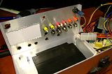
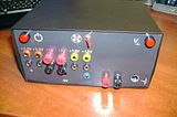
The switches: top left is POWER, top center is FAN ON/OFF and top right is VARIABLE VOLTAGE ON/OFF.
ok so what is the fourth switch for then and a step down convertor would work for me since 12 vdc is the highest that i would need for stuff it also would be less wiring
ReplyDeletei also want to know what the fourth switch is or is it an indicator light
ReplyDeleteThere is an indicator light and a switch. The switch switches the variable voltage from 1.25V to 10.75V to the stand-alone 1.25V - 21.75V. This is because the LM317 is connected to the GND and 12V line (giving maximum 10.75V) and the -12V and 12V line (giving an maximum of 21.75V BUT THE GND IS THE -12V NOW, which means you have to connect every ground of your circuit to the GND of the VARIABLE SUPPLY or -12V!! That is why it is stand-alone..). The yellow LED light turns on when the "stand-alone" function is activated to warn you.
ReplyDeleteTo have available the -5V pin connector means that you had an old atx psu, cause the latest ones doesn't have it. Keep up.
ReplyDeleteI hardly understand ... the process, if you pleas send me the full schmatic for this ..
ReplyDeleteOlso the volt cntroler the yellow wheel .. why i have to make other outputs if i setup the voltage regulator ?my inglish is bad i know . Its not my native language
I hardly understand ... the process, if you pleas send me the full schmatic for this ..
ReplyDeleteOlso the volt cntroler the yellow wheel .. why i have to make other outputs if i setup the voltage regulator ?my inglish is bad i know . Its not my native language
Thank you for another great article. Where else could anyone get that kind of information in such a perfect way of writing? I have a presentation next week, and I am on the look for such information. jy138
ReplyDelete